
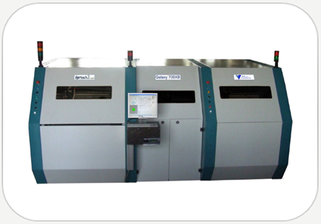
Galaxy 700XB is a line able to process Multilayers boards after the Press cycle
and before the Drilling process. Galaxy 700XB includes the following stations.
1. X-RAY Drilling module (Left)
2. Flash Cutting and Beveling module (Middle-Right)
3. Board Unloading station on trolley (Middle)
Options
a) Automatic loading system.
b) Bar code reader.
c) Board thickness measurement system.
d) Code Marking device (Serialization)
e) Deburring system for Slot cleaning.
![]()
Click on the Videos to see how the Galaxy 700XB Works

Process Description
- The boards are manually piles up on the trolley of loading station.
- A vacuum system pick up the board and after scrolling, place down it on the table of X-RAY station. If case of option, before place down the board on the x-ray table, can read the bar code, print a reference code on the copper and check the thickness.
- The X-RAY machine detects the 2 or 4 inner layer targets and after calculation drills 2 or more reference holes.
- The board is picked up again from the vacuum pad and translated on the Cutting/Beveling station.
- Two vertical opposed diamond cutters (blades), a couple on right and a couple on left side cuts the flash and bevels on the same time the two board sides. A third horizontal diamond blade bevels the “shoulder” of the edge.
- The board, outside the Beveling station, is 90° rotated and processed again for cuts and bevels the other two sides.
- The board is translated on the “Round Corner” station in order to round up the all the corners by axes circular interpolation. The panel is rotated at 90° for fourth steps.
- Before downloading the board on unloading trolley a special router clean the burr on the fourth slots
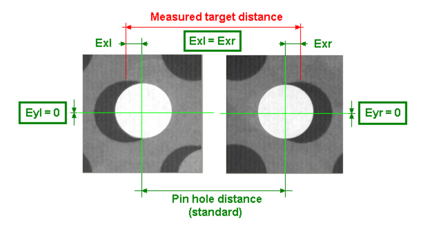
X-RAY DRILLING STATION PROCESS
In the following picture there is a simple example about the optimized position of two pinning holes respect to the position of two targets. In the following example, the left and right targets are measured at a higher distance than the nominal, which had to be the same of the pinning holes. Typically the axis of targets and holes is the main panel axis, which in the Antares machine is the X axis. The optimization process is so that the two pinning holes are drilled at the nominal distance, thus no longer at the target centers, but in a position, which allows the errors (annular rings) to be minimized on all the panel surface.